Designing Combinational Circuits
Combinational Circuits
A combinational circuit is one for which the output value is determined solely by the values of the inputs. Such a circuit can be represented by a truth table and computes a Boolean function. Desired characteristics of such a circuit are a minimum number of gates, simple rather than complex gates, and a minimum number of levels of gates. The first two characteristics can be stated as minimizing the number of gate inputs, which has the effect of minimizing cost. Minimizing the number of levels minimizes the number of gate delays and makes the circuit faster. For simple functions, it is possible to design a circuit by inspection of the function. For more complex functions, the appropriate circuit design may not be immediately obvious. Fortunately, there exists a completely mechanical way of designing a correct circuit for any Boolean function, that is, any function which can be represented by a truth table. A circuit designed in this way will be a two-level circuit, plus any inverters needed to form complement terms. Unless special steps are taken to simplify the expression which drives the circuit design, such a circuit will not necessarily have the minimum number of gate inputs.
Sum of Products
We need a function to use as an example. We will use the majority function. The majority function has the property that it is true when a majority of its inputs are true, and false when a majority of its inputs are false.
| A | B | C | F | |||
|---|---|---|---|---|---|---|
| 0 | 0 | 0 | 0 | |||
| 0 | 0 | 1 | 0 | |||
| 0 | 1 | 0 | 0 | |||
| 0 | 1 | 1 | 1 | |||
| 1 | 0 | 0 | 0 | |||
| 1 | 0 | 1 | 1 | |||
| 1 | 1 | 0 | 1 | |||
| 1 | 1 | 1 | 1 |
A three-input majority function will be true when any two (or all three) of its inputs are true. The truth table for the three-input majority function is shown at the right as Table 1. This represents a function F of three variables, A, B, and C. This truth table can be converted to a Boolean expression in standard form by identifying the rows which result in a value of one for F, writing the product AND of the variables for each such row, then writing the Boolean sum OR of the product terms. Such an expression is called a sum-of-products.* For example, the first result of one is the fourth row. A is zero and B and C are one, so the product term is ABC. The product terms for the other rows are formed in a similar way. The product terms are linked together with the Boolean OR. The sum-of-products expression for this truth table is: F = ABC+ABC+ABC+ABC. In this expression, the plus sign indicates Boolean OR, not addition.
This says that F is true when A is false and B and C are true or when B is false and A and C are true or when C is false and A and B are true or when all of A, B, and C are true. It also implies that F is false for all other combinations. It is possible to construct a circuit diagram directly from such an expression.
Circuit Design Using Sum of Products
A correct two-level circuit can be generated for any sum-of-products expression using the following steps:
 |
 |
||||||||||||||
- Provide an inverter for each variable.
- Provide an AND gate for each product term; the number of inputs required is determined by the number of variables in the product term
- Connect each AND gate according to the product term.
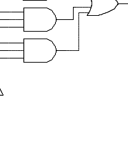
- Provide an OR gate for the output; the number of inputs required is determined by the number of AND gates.
The figure at the left shows the result of the first step. At the lower left are inputs
for each of the three variables, A, B, and C. For each variable, an inverter computes
its complement. When A is true, or one, A
is zero, and vice-versa. The vertical
wires provide for easy access to each variable and its complement.
Experiment with the inputs and observe what the LEDs show.
 |
|||||||||||||||||
 |
|||||||||||||||||
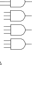
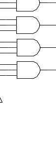
Because there are four product terms in the Boolean expression we want to compute, we need four AND gates. All four of them are shown in the figure, and the first one is wired.
We need to digress a bit and explain a detail of the diagram. There are vertical wires carrying signals for the three inputs and their complements, and horizontal wires connecting the AND gates. Wires that are connected are shown with a heavy dot at the connection. Wires which cross without a dot are not connected. For example, the topmost wire from the AND gate crosses four vertical wires without connection and is finally connected to A.
The first product term from our Boolean expression was ABC , so we wire the three inputs of the first AND gate to A , B, and C.
The AND gate will have an output of true for one
and only one combination of the inputs. What is it? Why?
 |
|||||||||||||||||
 |
 |
||||||||||||||||
Experiment with the circuit to verify that this is true. Compare the input combinations that generate an output of true with the truth table above.
Before you go on, be sure you understand what is happening with the AND
gates. There is one AND gate for each line in the truth table that
has a one in the output column. Each AND generates a one when the inputs
of the circuit match the inputs described on the corresponding line in the truth table.
 |
 |
||||||||||||||||
 |
|||||||||||||||||
Now we can address a question that may be troubling you. We paid explicit attention to the cases for which the function is true, and didn't address the cases for which it is not. You may be wondering whether this is an omission. It isn't. As you can see from Figure 3, each AND produces a one if the corresponding inputs are one. We don't need to explicitly represent the rows of the truth table that have outputs of zero because all of the AND gates produce outputs of zero in those cases. If the OR gate that generates the output has all zeros for input, it will generate a zero output.
Experiment with the final circuit to verify that it computes the majority function.
You can download
Digital Works and "wire up" your own combinational combinational circuits. I
have provided some sample circuits to get you started.
Limitations of Sum-of-Products
The sum-of-products method of combinational circuit design is completely mechanical, and it will always produce a correct two-level circuit. It does not always produce the optimal, or best circuit. Extracting a Boolean expression from the rows of a truth table produces an expression in minterm form. That means that every term of the expression contains every variable or its complement. Often, simpler expressions can represent the same function. In fact, the expression for the majority function that we just implemented can be simplified.
Simpler expressions mean fewer gates and therefore simpler circuits. Sometimes
a simplified expression allows the circuit to be arranged such that it is faster.
Minterm-form expressions can be simplified using manipulation with Boolean algebra,
Karnaugh maps, or other methods. So long as the resulting expression is in
sum-of-products form, this method can be used to construct a circuit that computes
it.
Something to Think About
We have said that hardware and software are logically equivalent, provided that there must actually be some hardware, however simple, to run the software. You have just worked through a software simulation of a very simple piece of hardware. If you built the actual circuit of Figure 4 in the logic lab, you would use eight gates, three switches, and one LED. The logic board assembly would take care of power and ground for you.The actual software that computes the majority function is only a few lines of JavaScript. You can use "view page source" to see what goes on behind the scenes. The majority computation function for Figure 4 is "compute_mj4_led_f()." There are a couple of hundred lines that toggle the inputs and keep track of the LED states for all the figures. Then there's the HTML that makes the pictures. All-in-all there are fewer than a thousand lines of "code" here.
Now think about the tens of thousands of lines in your Web browser and the hundreds of thousands of lines in your operating system. What about the Web server software and the operating system it runs under? The software in the Internet routers between you and the server...
How much of this software forms the logical equivalence of the hardware majority function? Is it just the JavaScript, and if not, where do you draw the line?
Cite this paper as:
Please take a moment to on this Web Lecture.
Table of Contents
![]() Previous: More Digital Logic
Gates
Previous: More Digital Logic
Gates![]()
![]() Next:
Combinational Logic Building Blocks
Next:
Combinational Logic Building Blocks
Originally published: 2000-09-09
Copyright © 2012 by Bob Brown. Some rights reserved.
This work is licensed under a Creative Commons Attribution-NonCommercial-ShareAlike 3.0 Unported License.
Last updated: 2012-10-21 16:34